What is Knob-and-Tube Wiring?
Knob-and-tube wiring is an early standardized method of electrical wiring in buildings, commonly used in North America from approximately 1880 to the 1940s and in Japan until the early 1960s [1]. The system consists of single-insulated copper conductors run within wall or ceiling cavities, passing through joist and stud drill-holes via protective porcelain insulating tubes, and supported along their length by nailed-down porcelain knob insulators [2][1].
This wiring method was invented by George H. Harris and Edward R. Callender, who received a patent for the system in the United States in 1888 [3]. The name directly derives from its two primary components: the porcelain knobs that secured and supported the wires, and the porcelain tubes that protected the wires as they passed through wooden framing members [3][3].
The fundamental design of knob-and-tube wiring employs two separate conductors—one hot and one neutral—typically kept 4 to 6 inches apart [2]. This separation allows the wires to dissipate heat efficiently into free air, giving the system a higher ampacity than modern wiring systems of the same gage [2]. Where conductors entered wiring devices such as lamps or switches, they were protected by flexible cloth or rubber insulation called “loom” [2][1].
Initially, insulation for these wires consisted of asphalt-saturated cotton cloth, though rubber insulation later became more common [1]. Wire splices in knob-and-tube installations were twisted together for mechanical strength, then soldered and wrapped with rubber insulating tape and friction tape (asphalt-saturated cloth), or sometimes made inside metal junction boxes [1].
Knob-and-tube wiring was gradually phased out after the 1940s as more modern alternatives emerged. The system became obsolete primarily due to the high cost of installation compared to power cables, which combined both power conductors in one run [1]. Furthermore, unlike modern electrical systems, knob-and-tube wiring lacks a ground wire [4], making it less suitable for contemporary electrical demands.
Despite being considered outdated by current standards, the installation of knob-and-tube wiring often required significant skill [2]. In fact, the original installation quality was frequently superior to that of modern Romex wiring, with the porcelain components having an almost unlimited lifespan [2]. Additionally, these wires were less likely than modern cables to be punctured by nails because they were held away from the framing [2].
At present, new concealed knob-and-tube installations are permitted in the United States only by special permission [1], as the system no longer meets modern electrical safety codes [5].
Key Components of Knob-and-Tube Wiring
The knob-and-tube electrical wiring system relied on several specialized components that worked together to provide insulation, support, and protection. Each component served a specific function within this early wiring method.
Porcelain knobs and tubes
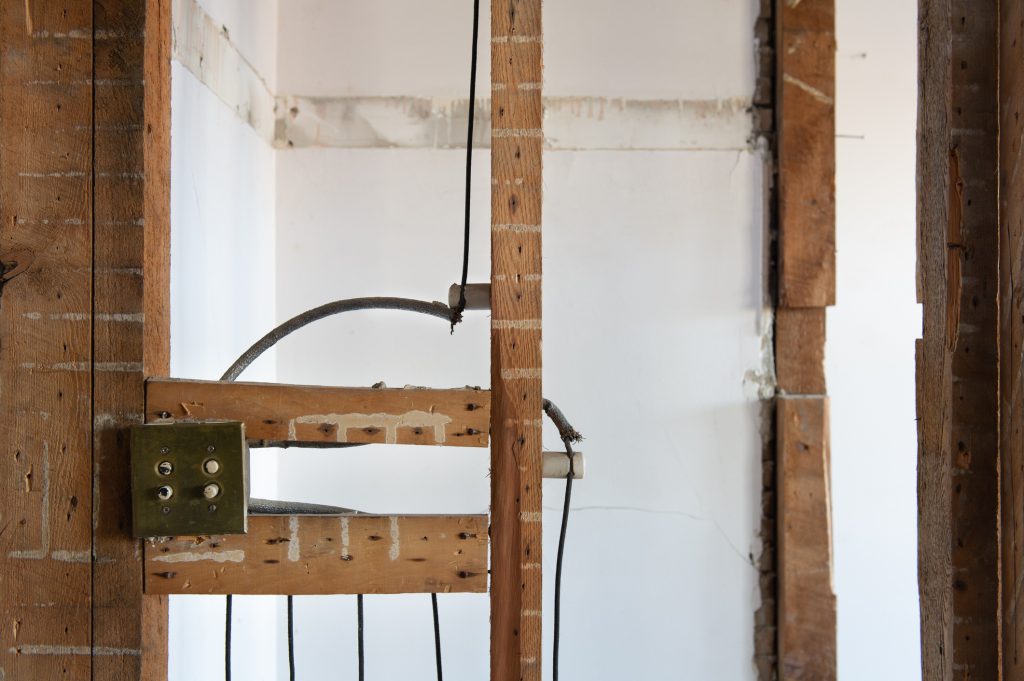
Porcelain knobs were cylindrical ceramic insulators primarily used to support and anchor electrical wires. These knobs were typically nailed directly into wall studs or floor joists, with a leather washer often cushioning the ceramic to reduce breakage during installation [3]. The knobs featured a circular groove running around their circumference, allowing wires to be wrapped around them and secured with tie wires [3]. This design kept the conductors suspended in air, enabling effective heat dissipation while maintaining separation from potentially combustible framework [3].
Porcelain tubes served as protective pathways for wires passing through framing members. These tubes were inserted into holes bored in wall studs or floor joists, preventing the wires from contacting the wood and being compressed as the house settled [3]. Additionally, ceramic tubes were sometimes utilized when wires crossed over each other, providing protection in case an upper wire broke and fell on the lower conductor [3].
Loom insulation
Loom was a woven flexible insulating sleeve used to provide additional protection at specific points in the wiring system. Originally made from asphalt-saturated cotton cloth, rubber eventually replaced cotton as the material of choice [6]. This protective covering was slipped over insulated wire whenever a wire passed over or under another wire, entered a metal device enclosure, or in other situations prescribed by code [3]. Essentially, loom protected connections at points where conductors entered devices such as lights or wall outlets [6].
Ceramic cleats and bushings
Ceramic cleats were block-shaped pieces that served a purpose similar to knobs except they were generally used for surface-mounted wiring [3]. Not all knob-and-tube installations utilized cleats [3]. Ceramic bushings protected each wire entering a metal device box when such enclosures were used [3]. Together with knobs and tubes, these components created a comprehensive insulation system with an almost unlimited lifespan [2].
Splice and junction methods
Unlike modern wiring systems, knob-and-tube splices were typically made outside of electrical junction boxes [1]. Standard practice involved twisting the bared wire ends securely, soldering the joint, applying tar, and wrapping with cloth-backed adhesive tape for insulation [4]. When a generic power outlet was desired, the wiring would run directly into the junction box through a tube of protective loom and a ceramic bushing [3]. Other ceramic pieces would typically be used as junction points between the wiring system proper and the more flexible cloth-clad wiring found in light fixtures or other permanent, hard-wired devices [3].
How Knob-and-Tube Wiring Was Installed
Installation of knob-and-tube wiring required meticulous planning and skilled craftsmanship, as this method involved carefully routing separate hot and neutral conductors throughout a structure’s framework. Qualified electricians typically placed these wiring systems in attics, basements, ceilings, walls, and other areas that remained out of the way [7].
The installation process began with drilling holes through wooden framing members. Subsequently, porcelain tubes were inserted into these holes to create protective pathways for the wires [8]. This strategic positioning along the center of joists and studs kept the wiring away from potential nail punctures [9]. Once the tubes were in place, insulated copper conductors were carefully threaded through them.
Throughout the installation, maintaining proper separation between conductors was paramount. The hot and neutral wires were consistently kept at least 3 inches apart except near fixture connections [9]. This deliberate separation reduced the risk of short-circuiting and minimized fire hazards [10].
For supporting the wires along their path, porcelain knobs were nailed directly into wall studs or floor joists. Accordingly, these knobs contained circular grooves where the wires were wrapped and secured with tie wires [11]. This method ensured the conductors remained suspended in air, allowing effective heat dissipation [11].
At points where wires entered fixtures like lamps or switches, flexible cloth or rubber insulation (loom) provided additional protection [3]. Whenever wires needed to cross over each other, ceramic tubes or loom was applied as a safeguard against potential damage [11].
Creating wire splices required particular attention. Electricians twisted the conductors together for mechanical strength, then soldered the joint before wrapping it with rubber insulating tape and friction tape [11]. Notably, knobs were placed within 6 inches of these splices to prevent stress on the connection [9].
The entire installation process demanded considerable skill – more so than modern Romex wiring [3]. This expertise ensured that the wires were never loose or placed on top of joists where they could be easily damaged [9]. Prior to the 1950s, this installation method was standard practice in residential construction throughout North America [12].
Advantages of Knob-and-Tube Wiring
Despite being considered antiquated by today’s standards, knob and tube electrical wiring offered several significant advantages that made it the preferred wiring method for decades.
A principal benefit was the system’s superior heat dissipation capabilities. With hot and neutral wires typically separated by 4 to 6 inches, knob-and-tube installations allowed conductors to readily dissipate heat into free air, resulting in higher ampacity than modern wiring systems of equivalent gage [3]. This separation minimized the risk of overheating even under significant electrical loads.
The structural design of knob-and-tube wiring provided inherent protection against certain types of damage. Since wires were suspended away from structural framing members, they remained less vulnerable to accidental punctures from nails or screws during building renovations [3]. This positioning effectively prevented many common causes of electrical shorts found in contemporary systems.
Furthermore, the materials used in knob-and-tube systems offered exceptional durability. The porcelain components—including knobs, tubes, and cleats—possessed an almost unlimited lifespan [3]. These ceramic elements maintained their insulating properties indefinitely, remaining functional for many decades without degradation.
Additionally, copper conductors in knob-and-tube installations were frequently of larger gage than those used in modern wiring, allowing them to conduct electricity with less resistance and generating less heat as current flowed through them [2]. This characteristic further enhanced the system’s safety and efficiency.
The installation process itself required considerable expertise, often resulting in craftsmanship superior to that of contemporary Romex wiring installations [3]. Skilled electricians meticulously planned and executed these systems, creating reliable electrical infrastructure that has endured in many cases for more than a century.
Another practical advantage was the visibility of connections throughout the system. With junction points exposed rather than concealed behind walls, identifying potential issues became more straightforward for maintenance purposes [6]. This transparency allowed for easier troubleshooting and repairs when necessary.
Although modern electrical codes have rendered new knob-and-tube installations obsolete, these inherent advantages explain why many historical systems continue to function safely after decades of service.
Disadvantages and Safety Concerns
While knob-and-tube wiring functioned adequately for early electrical needs, several inherent flaws make it problematic for contemporary usage. These safety concerns have led to its obsolescence in modern electrical systems.
No grounding wire
Knob-and-tube installations fundamentally lack a grounding conductor, which represents a critical safety deficiency. Without proper grounding, there exists no safe path for fault currents, significantly increasing the risk of electrical shock and potential fires. This absence makes the system incompatible with modern three-pronged appliances that require grounding for safe operation. Consequently, these devices may short out, creating shock hazards for users and potential fire risks. Many certified electricians recommend full system replacement primarily because of this missing safety feature.
Aging insulation and fire risk
The original rubber or cloth insulation surrounding knob-and-tube conductors deteriorates substantially over time. After decades of exposure to heat fluctuations and humidity, especially in attics and crawlspaces, this material becomes brittle, cracks, or completely disintegrates. This degradation exposes live wires, creating serious electrical hazards. Furthermore, modern building insulation placed in contact with knob-and-tube wiring presents a major fire risk. Since these wires were designed to dissipate heat in open air, covering them with insulation traps heat, potentially igniting surrounding materials.
Overfusing and circuit overload
Knob-and-tube wiring was never designed to handle the electrical demands of contemporary appliances and electronics. A common dangerous practice involved installing fuses with higher amperage ratings (overfusing) to prevent frequent blown fuses. This modification allowed excessive current to flow through wiring not rated for such loads, causing overheating and wire damage. Circuit overloads manifest through warning signs including flickering lights, buzzing outlets, warm switch plates, and burning odors—all indicators of potential fire hazards.
Unsafe modifications
Throughout their long service lives, knob-and-tube systems have frequently been modified by untrained individuals. These amateur alterations include improper splicing of modern wiring into old circuits without junction boxes, using inappropriate materials like masking tape instead of electrical tape, and creating hazardous connections. Moreover, inexperienced homeowners often damaged insulation when bending wires, exposing bare conductors. These modifications frequently violate electrical codes and substantially increase fire risks, making them perhaps the most concerning aspect of existing knob-and-tube installations.
Where Knob-and-Tube Wiring Was Used
Geographically, knob and tube electrical wiring saw widespread adoption primarily in two major regions, with some limited modern applications still permitted today.
North America (1880s–1940s)
The knob-and-tube system first gained prominence throughout North America beginning in the late 1880s. Following the 1888 patent by George H. Harris and Edward R. Callender [10], this wiring method became standard practice across the continent. The system’s popularity stemmed partly from economic considerations—installing knob and tube wiring cost approximately half as much as conduit systems with armored cable [13]. Despite newer technologies emerging by the 1940s, some electricians continued installing knob and tube wiring in new construction into the 1970s [13].
Japan (until 1960s)
Outside North America, Japan adopted knob and tube wiring extensively. Known locally as “Gaishi-biki kōji” (碍子引き工事), this system remained common in Japanese residential buildings until the early 1960s [11]. Unlike North American installations, Japanese regulations typically prohibited concealing knob-and-tube wiring behind walls unless inspection panels provided accessibility [11]. Japan’s prevalence of wood-framed housing, combined with imported electrical technologies from the United States, made this wiring method particularly suitable.
Modern code exceptions
Currently, most jurisdictions prohibit new knob-and-tube installations. Nevertheless, the 2008 National Electrical Code permits this wiring method by “special permission” in certain circumstances [3]. Various jurisdictions handle existing knob-and-tube wiring differently—some require removal from all accessible locations, whereas others mandate safety inspections without removal [3]. California represents a notable exception, allowing insulation to contact knob-and-tube wiring provided specific conditions are met, including certification by a licensed electrical contractor [3].
References
[1] – https://www.novahomeinspections.com/knob–tube-electrical-info.html
[2] – https://reliableair.com/blog/knob-and-tube-wiring-should-you-replace-it
[3] – https://www.nachi.org/knob-and-tube.htm
[4] – https://www.servicepluselectrical.com/everything-you-should-know-about-knob-and-tube-wiring
[5] – https://www.mncee.org/dealing-knob-and-tube-wiring
[6] – https://ausecoelectrical.com.au/articles/knob-and-tube-wiring/
[7] – https://www.daltonphc.com/blog/electrical-services/a-guide-to-knob-and-tube-wiring/
[8] – https://tappselectric.com/a-guide-to-knob-and-tube-wiring/
[9] – https://historicbldgs.com/knobandtube.html
[10] – https://benchmarkseattle.com/the-fascinating-history-of-knob-and-tube-wiring/
[11] – https://en.wikipedia.org/wiki/Knob-and-tube_wiring
[12] – https://tntelectric-co.com/ultimate-guide-to-knob-and-tube-rewire-process/
[13] – https://allwireelectric.com/the-problem-with-knob-and-tube-systems-why-you-should-rewire/